A Technician’s Guide: The Cedar Intel MB 13269-1 Disable GPU Conversion
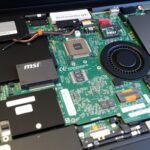
If you’re a repair technician, you’ve likely encountered this frustrating scenario: a laptop, often a Dell Inspiron or Vostro model using the Cedar Intel MB 13269-1 motherboard, powers on but shows no display, displays strange artifacts, or constantly crashes. The most common culprit is a failing discrete graphics chip (dGPU). While replacing the GPU can be expensive and unreliable, a more permanent and cost-effective solution exists: disabling the faulty chip entirely and switching the board to UMA (Unified Memory Architecture) or integrated graphics.
This guide provides a detailed walkthrough of the cedar intel mb 13269-1 disable gpu hardware modification process, designed for technicians with soldering experience.
Why Disable the Discrete GPU?
Discrete GPUs, especially older models, are prone to failure due to overheating, which can cause the BGA solder connections underneath the chip to crack and fail. Disabling it offers several key advantages:
- Cost-Effective Repair: It saves the high cost of a new GPU chip and reballing services.
- Reliability: It provides a permanent fix for GPU-related display issues.
- Improved Thermals: The laptop runs cooler as the power-hungry dGPU is no longer active.
Tools and Preparation
Before you begin, ensure you have the following:
- A fine-tip soldering iron and hot air station.
- Good quality soldering flux and tweezers.
- A multimeter for verification.
- The schematic for the Cedar Intel MB 13269-1 motherboard (essential for locating components).
Step-by-Step Guide: The Hardware Modification
The process involves changing the motherboard’s hardware configuration by moving or removing specific “strap resistors.” These resistors tell the system’s firmware whether to initialize the discrete GPU or just the integrated Intel HD graphics.
Warning: This is an advanced procedure. Proceed with caution and at your own risk.
- Disconnect All Power: Unplug the AC adapter and disconnect the internal battery. Press the power button for 15 seconds to discharge any residual power.
- Locate the Strap Resistors: Using your schematic, search for the GPU strap configuration options. These are often located near the PCH (Platform Controller Hub) or the GPU itself. The goal of the cedar intel mb 13269-1 disable gpu process is to switch these straps from “discrete” to “UMA” mode.
- Perform the Resistor Conversion (Example):The exact resistor changes can vary slightly between board revisions, but a common procedure for this board is as follows:
- Identify and Remove: Locate the resistor that enables the discrete graphics. For example, you might need to remove a resistor at position
R205. - Identify and Shift/Add: Locate a resistor that enables UMA graphics. For example, you may need to move the resistor from
R205to an empty pad at positionR206. If no resistor is available to move, you can use a 0-ohm resistor or a small solder bridge on the UMA pads.
- Identify and Remove: Locate the resistor that enables the discrete graphics. For example, you might need to remove a resistor at position
- Disconnect Power to the GPU: This is a crucial step to ensure the faulty GPU doesn’t draw any power.
- Locate the main power coils that supply voltage to the GPU core and memory. On the schematic, these might be labeled
PL501andPL502. - Carefully desolder and remove these coils from the motherboard. This physically cuts off the main power supply to the GPU, completing the cedar intel mb 13269-1 disable gpu modification.
- Locate the main power coils that supply voltage to the GPU core and memory. On the schematic, these might be labeled
Post-Modification Steps
Once the hardware changes are complete, you need to clean up the software.
- Uninstall Old Drivers: Before booting into Windows, it’s highly recommended to use a tool like DDU (Display Driver Uninstaller) in Safe Mode to completely remove all old NVIDIA or AMD graphics drivers.
- Install Intel Drivers: Allow Windows to boot and install the appropriate Intel HD Graphics drivers for the CPU (e.g., Intel I3-4005U).
By following these instructions, you can successfully perform the cedar intel mb 13269-1 disable gpu conversion, breathing new life into a laptop that was otherwise destined for the scrap heap. This reliable fix turns a complex problem into a manageable and profitable repair.
(Article Content Ends)
Article 2: LA-D704P Boardview
Focus Keyword: la-d704p boardview
Title: LA-D704P Boardview: The Ultimate Guide for Motherboard Repair
Slug: la-d704p-boardview-repair-guide
Meta Description: Unlock motherboard repair with our guide to the LA-D704P boardview. Learn what a .brd file is, where to find it, and how to use it for effective troubleshooting.
(Article Content Begins)
The Technician’s Secret Weapon: A Guide to Using the LA-D704P Boardview
Trying to diagnose a fault on a modern laptop motherboard like the Compal LA-D704P without the right tools can feel impossible. You might know a power rail is shorted, but with hundreds of tiny, unmarked components, where do you even begin to look? This is where the LA-D704P boardview file becomes the most valuable tool on your workbench.
Unlike a schematic that shows electrical connections in abstract diagrams, a boardview is an interactive map of the motherboard’s physical layout. This guide will explain what a boardview is, why it’s essential, and how to use it to make your repairs faster and more accurate.
What is a Boardview and Why is it Essential?
A boardview file (often with a .brd, .cad, or .fz extension) is a digital representation of the printed circuit board (PCB).1 When opened in compatible software, it allows you to:
- Instantly Locate Components: Simply type in a component designator (like
PU301orC215) and the software will highlight it on the board. - Trace Physical Connections (Nets): Click on any pin of a component, and the boardview will highlight every single point on the board that is electrically connected to it.
- Identify Test Points: Easily find convenient points to measure voltages or check for continuity.
- Diagnose Short Circuits: Quickly see all the components connected to a shorted power rail, dramatically narrowing down the list of potential culprits.
For any complex repair, having the LA-D704P boardview is not a luxury; it’s a necessity.
How to Find and Open the Boardview File
- Finding the File: The first step is acquiring the correct LA-D704P boardview file. Since these are proprietary, they are not usually released publicly by manufacturers. However, they can often be found on:
- Specialized online repair forums (e.g., Badcaps).
- Paid schematic and boardview websites.
- Online communities for laptop technicians.
- Important: Ensure the version of the boardview matches the revision number printed on your motherboard (e.g., Rev 1.0, Rev 2.0).
- Choosing Boardview Software: You’ll need a viewer application to open the file. Several free and powerful options are available:
- OpenBoardView (highly recommended, open-source)2
- FZ-Viewer
- BoardViewer
- OpenBoardView (highly recommended, open-source)2
Practical Guide: Troubleshooting with the LA-D704P Boardview
Let’s imagine a common problem: a dead Lenovo laptop with an LA-D704P motherboard that has a short circuit on the main 19V power rail.
- Confirm the Short: Using a multimeter in resistance mode, you confirm a low resistance to ground on the main power rail just after the DC-in jack.
- Open the Boardview: Launch your software and open the LA-D704P boardview file.
- Locate the Power Rail: Find the main DC-in jack on the boardview. Click on the pin that carries the 19V supply (often labeled
+VINor similar). - Analyze the Net: The software will instantly highlight every single component connected to this 19V rail across the entire motherboard. This will include dozens of ceramic capacitors, which are the most common components to fail and cause a short.
- Inject Voltage (Optional Advanced Step): With the net highlighted, you can use a lab power supply to inject a low voltage (e.g., 1V) and limited current into the rail. The shorted component will get hot, and using the boardview, you can quickly check the highlighted components with thermal paper or isopropyl alcohol to find exactly which one is heating up.
Without the LA-D704P boardview, this process would involve blindly removing components one by one—a slow, frustrating, and risky method. With the boardview, you can diagnose the issue with surgical precision in a matter of minutes. Whether you are a seasoned professional or an aspiring technician, mastering the use of the LA-D704P boardview will elevate your repair skills to the next level.
(Article Content Ends)