We’re going to take a look at the Cedar Intel MB 13269-1 schematic. If you’re working with this board, having this document is pretty helpful. It shows us how everything is put together, which can save us a lot of time when we’re trying to figure things out or fix a problem. So, let’s get into what this cedar intel mb 13269-1 schematic actually shows us and why it’s important for anyone tinkering with this hardware.
Key Takeaways
- The cedar intel mb 13269-1 schematic breaks down the board’s main parts.
- It shows how the processor, memory, and chipset connect and work together.
- We can see how power gets to the different parts of the board and how it’s managed.
- The document details all the ways you can connect other devices to the board.
- It’s a good resource for figuring out why something isn’t working and how to fix it.
Understanding The Cedar Intel MB 13269-1 Schematic
Alright folks, let’s get started with the Cedar Intel MB 13269-1 schematic. We’re going to break down what this document is all about and how we can use it to our advantage. Think of this schematic as our roadmap for the motherboard. It shows us all the connections, the different parts, and how they talk to each other. It’s not just a bunch of lines and symbols; it’s the blueprint that makes this whole thing work.
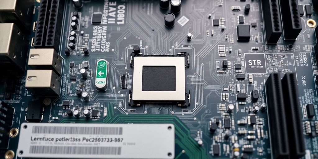
Key Components Overview
First off, we need to know what the main players are on this board. The schematic will point out:
- The CPU socket and its connections.
- The RAM slots and how they’re wired.
- The various power management chips.
- The different input/output controllers.
- The BIOS chip and its support circuitry.
Knowing these parts is step one to understanding the whole system.
Purpose of the Schematic
So, why do we even have this document? Well, its main job is to show us the electrical design of the motherboard. It’s used for a few things:
- Design and Development: Engineers use it to create and modify the board.
- Manufacturing: It guides the assembly process.
- Troubleshooting and Repair: This is where it gets really useful for us. If something goes wrong, the schematic helps us figure out where the problem might be.
It’s the definitive source for how everything is supposed to be connected.
Navigating the Document
Looking at a schematic for the first time can be a bit much. There are a lot of symbols and lines. But don’t worry, we’ll get the hang of it. Here’s how we can approach it:
- Start with the Index: Most schematics have an index that lists all the major sections and the pages they’re on. Find the parts you’re interested in first.
- Follow the Traces: See how signals travel from one component to another. This is how you trace a connection.
- Look for Labels: Components and nets usually have labels that tell you what they are or what they do. Pay attention to these.
We’ll get better at reading it the more we use it. It’s all about practice.
Core System Architecture Explained
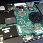
Alright, let’s get into the nitty-gritty of how this Cedar Intel MB 13269-1 motherboard is put together. It’s not just a bunch of parts; there’s a whole system working here.
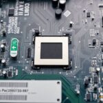
Processor Integration
So, the brain of this whole operation is the Intel processor. On this particular board, we’re looking at an Intel I3-4005U. This chip handles all the main calculations and tells everything else what to do. It’s soldered right onto the motherboard, meaning it’s not something you can easily swap out. Think of it as the engine of your laptop, pretty central to its performance. We can see how it connects to other parts of the board through various traces, which are like tiny highways for data.
Memory Subsystem Design
Next up is the memory, or RAM. This board uses DDR3 memory. You’ll usually find a couple of slots for these memory sticks. The processor needs quick access to data to run programs smoothly, and that’s where RAM comes in. The faster and more RAM you have, the better your laptop can multitask. The schematic shows us exactly how the memory controller, which is often part of the processor itself or the chipset, communicates with the RAM modules. It details the data and address buses, which are the pathways for information going to and from the memory. Getting the right type of RAM is important, and this board specifies DDR3, so don’t try to put DDR4 in there!
Chipset Functionality
The chipset is like the traffic cop for the motherboard. It manages the flow of data between the processor, memory, and all the other peripherals like USB ports, storage drives, and graphics. On this board, the chipset works closely with the Intel processor to make sure everything communicates efficiently. It often handles tasks that the CPU doesn’t need to worry about directly, freeing up the processor for more demanding jobs. The schematic will show you how the chipset connects to everything, including the various I/O controllers. It’s a pretty complex piece of the puzzle, really tying all the different components together so they can work as a team. You can find more details about this specific motherboard, including its processor and memory support, on the product listing.
Power Delivery Network Analysis
Alright, let’s talk about how this Cedar Intel MB 13269-1 board gets its juice. The Power Delivery Network, or PDN, is basically the whole system that makes sure all the different parts of the motherboard get the right amount of power, at the right voltage, and at the right time. It’s pretty complex, honestly.
Voltage Regulation Stages
When power comes in, usually from the adapter or battery, it’s not at the voltages the CPU or RAM needs. So, the PDN has several stages of voltage regulators. Think of them like a series of steps, each one lowering the voltage a bit more until it’s just right for each component. We’ll see things like buck converters and LDOs (low-dropout regulators) doing this work. Each regulator is designed for a specific voltage rail, like Vcore for the CPU or VDDQ for memory. You’ll find these regulators scattered across the board, often near the components they serve.
Power Sequencing Logic
It’s not just about having the right voltage; it’s also about the order in which things get powered up. The power sequencing logic dictates this. Certain chips need to be on before others can start. If this order is messed up, the system might not boot, or worse, you could damage components. The schematic shows us the control signals and the order in which power rails are enabled. It’s like a carefully choreographed dance for the electricity.
Battery Management Integration
For laptops, the battery is a big part of the power story. The schematic will show how the battery connects and how the system manages charging and discharging. This includes the Battery Management System (BMS) chip, which monitors battery health, temperature, and charge level. We can trace the charging circuits and see how the system switches between AC power and battery power.
Input/Output Interfaces Detailed
Let’s talk about how everything connects on the Cedar Intel MB 13269-1 board. This section of the schematic is where we get into the nitty-gritty of all the ports and connectors.
Peripheral Connectivity
This is where we see all the bits and pieces that let the motherboard talk to the outside world. Think USB ports, audio jacks, and things like that. We’ll look at:
- How the USB controllers are wired up.
- The audio codec and its connections.
- Any other smaller ports like card readers or special connectors.
Understanding these connections helps us figure out what devices can be plugged in and how they’ll work.
Display Output Pathways
If you’re looking at how the video signal gets out, this is your spot. It covers everything from the graphics processor to the actual display connectors.
- HDMI and DisplayPort connections.
- Internal display connectors for laptops.
- The path from the CPU’s graphics to the output ports.
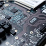
Storage Interface Connections
This part of the schematic shows us how we hook up our storage devices, like SSDs and hard drives. We’ll check out:
- SATA ports and their controllers.
- M.2 slots and NVMe connections.
- How data moves between storage and the rest of the system.
Troubleshooting With The Schematic
When things go wrong with our Cedar Intel MB 13269-1 board, the schematic becomes our best friend. It’s not just a bunch of lines and symbols; it’s a map to figure out what’s happening under the hood.
Common Failure Points
We often see issues pop up in a few key areas. Knowing these can save us a lot of time:
- Power delivery problems: This is a big one. If the board isn’t getting the right voltages, or if they’re unstable, nothing else will work right. We’ll look for shorts or bad voltage regulators.
- Memory issues: RAM problems can cause all sorts of weird behavior, from boot failures to random crashes. Checking the memory traces and the chips themselves is usually on the list.
- CPU-related faults: If the processor isn’t communicating correctly, or if it’s overheating, that’s a showstopper. We’ll check the connections and any thermal management components.
- Peripheral conflicts: Sometimes, a faulty USB device or a bad connection on an expansion card can mess things up. Isolating these can be tricky.
Diagnostic Signal Tracing
This is where the schematic really shines. We can follow signals from one point to another to see where things break down. For example, if a component isn’t powering up, we can trace the power rail back to its source using the schematic. We’re looking for breaks in the traces, bad solder joints, or faulty components along the path. It’s like being a detective, but with a blueprint.
Component Identification for Repair
When we find a bad component, the schematic tells us exactly what it is. We can find its part number, its value (like resistance or capacitance), and where it sits on the board. This makes finding a replacement so much easier. Without the schematic, guessing the right component would be a nightmare. We can also see what other components are connected to it, which helps us understand the impact of replacing it and if we need to check anything else nearby.
Advanced Features and Customization
Alright, let’s talk about the cool stuff beyond the basic setup with the Cedar Intel MB 13269-1 schematic. We’re going to look at how we can push this board a bit further or tweak it for specific needs.
Expansion Slot Utilization
So, you’ve got these expansion slots, right? They’re not just there for show. We can use them to add all sorts of things. Think about adding extra Wi-Fi cards, maybe some specialized data acquisition hardware, or even a secondary graphics card if the main setup allows for it. It really depends on what you’re trying to achieve with your system. We need to check the schematic to see which pins are connected to what and what kind of signals are available on each slot. It’s like finding hidden potential in the board.
Firmware Interface Points
Now, the firmware is like the brain of the operation. The schematic shows us where we can connect to it. This is super handy if we need to update the BIOS, maybe flash a custom firmware, or even just poke around and see what’s going on under the hood. There are usually specific headers or test points marked on the board that give us access to the firmware interface. Understanding these points is key if you ever need to recover from a bad flash or want to experiment with different firmware versions. We’ll want to pay close attention to the pinouts and voltage levels to make sure we don’t fry anything.
Security Feature Implementation
Security is a big deal these days, and this board has some features built-in that we can look at. The schematic can show us how things like Trusted Platform Module (TPM) headers are connected, or where specific security-related jumpers or switches might be. If you’re building something that needs an extra layer of protection, knowing where these components are and how they’re wired up is pretty important. It might involve setting up specific boot sequences or enabling certain hardware security modules. We can trace the connections to see how these security features interact with the rest of the system.
Wrapping Things Up
So, that’s pretty much it for the Cedar Intel MB 13269-1 schematic. We went through a lot of the main parts, and hopefully, it makes a bit more sense now. It’s not always easy to figure out these diagrams, but breaking them down like this helps. If you’re working on something similar, maybe this guide gave you a few ideas or at least showed you where to start looking. We’re still learning ourselves, so if you found something cool or have tips, let us know. Happy tinkering!
Frequently Asked Questions
What exactly is this schematic thing?
Think of the schematic as a super detailed map for our computer’s motherboard. It shows us exactly where every single part is connected and how they talk to each other. It’s like the blueprint for the whole system, helping us understand how everything works together.
How does the processor connect to the memory?
We use this map to figure out how the main brain, the processor, connects to the computer’s memory. It shows us the pathways for data to flow back and forth, which is super important for how fast our computer can think.
How does the motherboard get its power?
This part of the map explains how we get power to all the different chips on the board. It shows us how the battery’s power gets changed into the right voltages that each part needs to run, kind of like making sure everyone gets the right amount of juice.
What about plugging in our devices?
We can look at the schematic to see how things like USB ports, our screen connection, and the drives where we store our files are hooked up. It’s our guide to understanding all the ways we can plug stuff into our computer.
Can this map help us fix problems?
If something goes wrong, like a part not working, this map is our best friend. We can follow the connections to see where the problem might be, or find the exact name of a part we need to replace. It makes fixing things much easier.
Can we add new things or make changes with this map?
Yep, it can! We can use the schematic to see if there are special spots for adding extra parts, or how to update the computer’s basic software. It even shows us how security features are built-in, giving us a peek into how our computer stays safe.
To truly appreciate its value, let’s walk through a hypothetical repair scenario. Imagine a laptop with this motherboard powers on—the fan spins, and indicator lights are on—but there is no image on the screen (a “no display” fault). After basic checks like testing an external monitor fail, a technician’s most crucial tool becomes the Cedar Intel MB 13269-1 Schematic.
The first step is to open the document and navigate to the display connector section, usually labeled LVDS or eDP. By examining this part of the diagram, the technician can identify the exact pins that supply power to the screen panel, such as LCD_VDD. Using a multimeter, they discover there is no voltage on this pin. This is a critical clue, and the Cedar Intel MB 13269-1 Schematic is essential for tracing this power rail back to its source. The trace might lead to a specific power switch (a small MOSFET) that enables power to the display.
Following the circuit lines on the diagram, the technician pinpoints a component, let’s call it Q25, as the likely culprit. Without the Cedar Intel MB 13269-1 Schematic, finding this tiny component among hundreds of others would be like finding a needle in a haystack. The schematic provides the component’s board designator (Q25), its part number, and its characteristics, making it easy to test and find a replacement. A quick test confirms the MOSFET is faulty.
After replacing the component, the technician must verify the repair. They once again refer to the Cedar Intel MB 13269-1 Schematic to confirm the correct voltage is now present at the LCD_VDD pin on the display connector. This cross-referencing is a vital step to ensure the problem is truly solved and no other issues were created. The detailed information within the Cedar Intel MB 13269-1 Schematic allows for such a precise and efficient repair process.
This entire diagnostic journey, from identifying the problem area to pinpointing the exact faulty component, would be significantly more difficult and time-consuming without access to a proper diagram. This case study underscores why the Cedar Intel MB 13269-1 Schematic is not just a document, but an indispensable asset for any serious board-level technician. Ultimately, the successful repair is a testament to the power of having the right information, and for this board, that information is contained within the Cedar Intel MB 13269-1 Schematic.